Gogo AVANCE™ Integration Kits
Product Details
We are pleased to offer turnkey integration kits for the Gogo AVANCE™ L3/L5/L5i Air-To-Ground (ATG) system. These kits are ideal for all installations where customized engineering is expensive and unnecessary.
features & options
- ATG, WiFi & TM Coax Cable Kits: Custom lengths and fully & partially terminated coaxial cable options available
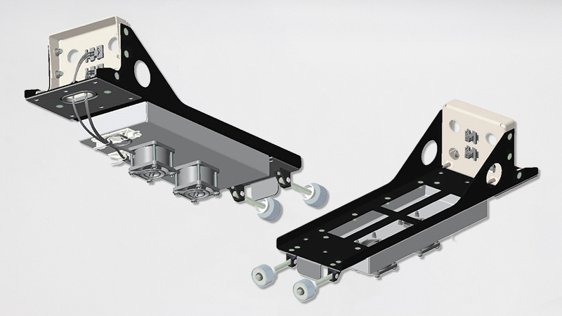
- AVANCE™ Trays: Designed and qualified per AVANCE™ specifications; equipped with dual fans to properly cool the system, as well as a relay switch that activates the fan power when the LRU is installed. Additional custom options are available upon request.
- Ethernet, Data Bus & USB Harness Kits: Custom length & partially terminated harnesses
Amphenol CIT’s engineering team is available to answer questions and provide guidance on selecting the perfect combination of components for your specific application.
Our in-house integrated engineering teams are ready to take on your greatest challenges.
Specifications, Drawings & Related Literature
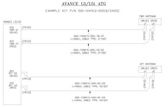
ATG coax cable kits are engineered to the length you require and optimized for loss and attenuation, depending on your installation length. Various cable types and connector variations (straight or right-angle) are available to optimize your installation needs, including fully terminated and partially terminated options. The kits are designed for both Omni and Dual antenna configurations — just plug and play!
Example Configuration: P/N 500-104913-2001B/5405C
- Fwd Cable Length (in) = 200
- Fwd Cable Type = P/N: 311901 = 1
- Fwd TNC Connector Configuration = Straight (V1, H1), Right Angle (J1, J2*) = B
- Aft Cable Length (in) = 540
- Aft Cable Type = P/N: 421201 = 5
- Aft TNC Connector Configuration = Right Angle (V2, H2), Right Angle (J1, J2*) = C
*For Dual Antenna Directional configuration, J4 is used instead of J2
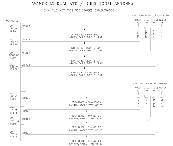
ATG coax cable kits are engineered to specify your required length and optimized for loss and attenuation dependent upon your installation length. Various cable types and connector variations (straight or right angle) are available to optimize your installation needs, as both fully terminated and partially terminated options. The kits are designed for both Omni and Dual antenna configurations — just plug and play!
dual atg/directional antenna
Example Configuration: P/N: 500-104821-2001B/5405C
- Fwd Cable Length (in) = 200
- Fwd Cable Type = P/N: 311901 = 1
- Fwd TNC Connector Configuration = Straight (H1, V1, H2, V2), Right Angle (J2, J1, J4, J3) = B
- Aft Cable Length (in) = 540
- Aft Cable Type = P/N: 421201 = 5
- Aft TNC Connector Configuration = Right Angle (H3, V3, H4, V4), Right Angle (J2, J1, J4, J3) = C
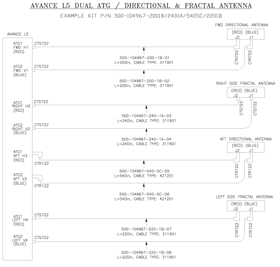
dual atg/directional & fractal antenna
Example Configuration: P/N: 500-104967-2001B/2401A/5405C/2201B
- Fwd Cable Length (in) = 200
- Fwd Cable Type = P/N: 311901 = 1
- Fwd TNC Connector Configuration = Straight (H1, V1), Right Angle (J2, J1) = B
- Right Cable Length (in) = 240
- Right Cable Type = P/N: 311901 = 1
- Right TNC Connector Configuration = Straight (H2, V2), Straight (J2, J1) = A
- Aft Cable Length (in) = 540
- Aft Cable Type = P/N: 421201 = 5
- Aft TNC Connector Configuration = Right Angle (H3, V3), Right Angle (J2, J1) = C
- Left Cable Length (in) = 220
- Left Cable Type = P/N: 311901 = 1
- Left TNC Connector Configuration = Straight (H4, V4), Right Angle (J2, J1) = B
ATG coax cable kits are engineered to the length you require and are optimized for loss and attenuation based on your installation length. Various cable types and connector variations (straight or right-angle) are available to optimize your installation needs, including fully terminated and partially terminated options. The kits are designed for both Omni and Dual antenna configurations — just plug and play!
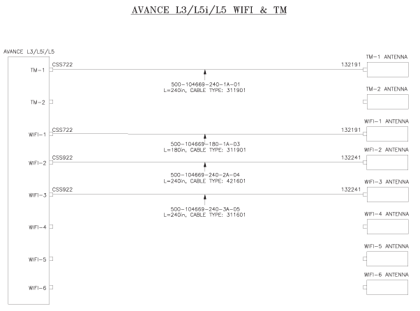
Please refer to the configurator worksheet and the linked drawing to generate your cables based on the number of TM & Wi-Fi antennas required. SMA coax connectors are automatically chosen based on cable type and connector configuration. Cables are ordered à la carte.
- TM-1 ☐ 500-104669-XXX-XA-01
- TM-2 ☐ 500-104669-XXX-XA-02
- WiFi-1 ☐ 500-104669-XXX-XA-03
- WiFi-2 ☐ 500-104669-XXX-XA-04
- WiFi-3 ☐ 500-104669-XXX-XA-05
- WiFi-4 ☐ 500-104669-XXX-XA-06
- WiFi-5 ☐ 500-104669-XXX-XA-07
- WiFi-6 ☐ 500-104669-XXX-XA-08
Example Configuration: P/N: 500-104821-2001B/5405C
- TM-1 ☒ 500-104669-240-1A-01 — 240 inches, Straight/Straight, 311901
- TM-2 ☐ N/A
- WiFi-1 ☒ 500-104669-180-1A-03 — 180 inches, Straight/Straight, 311901
- WiFi-2 ☒ 500-104669-240-2A-04 — 240 inches, Straight/Straight, 421601
- WiFi-3 ☒ 500-104669-240-3A-05 — 240 inches, Straight/Straight, 311601
- WiFi-4 ☐ N/A
- WiFi-5 ☐ N/A
- WiFi-6 ☐ N/A
Connector harness kits are engineered to specify your desired lengths for each aircraft bus location and system specified in the installation manual. Please refer to the following worksheets to build your P1, P2, & P3 harnesses. All harnesses are terminated at the connector end and capped at the A/C end. Ethernet, Data Bus, USB, & Discrete wires specified in the installation manual are used to populate the connector harnesses. The harnesses also include the mating backshells for P1, P2, & P3. Additional bulk wire & cable can be purchased separately from the harnesses to accommodate additional Ethernet and Data Bus connections needed to complete your installation.
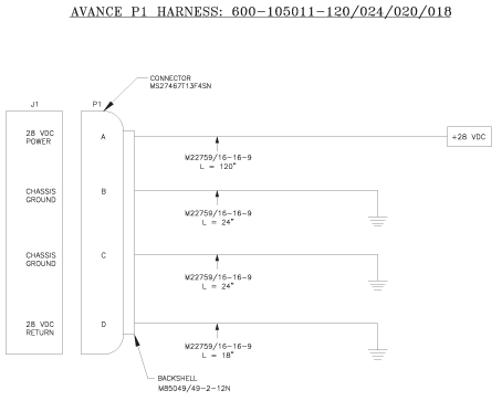
p1 harness
Example Configuration: P/N 600-105011-120/024/020/018
- Length to 28 VDC Power Source = 120 in
- Length to Ground #1 = 24 in
- Length to Ground #2 = 20 in
- Length to Ground #3 = 18 in
- M22759/16-16-9 (Qty 4)
- P1 Connector = MS27467T13F4S or E
- P1 Connector Backshell = M85049/49-2-12N
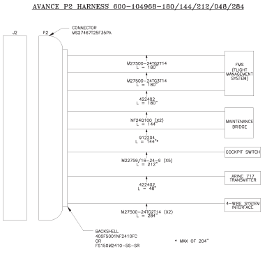
p2 harness
Example Configuration: P/N 600-104968-180/144/212/048/284
- Length to FMS = 180 in
» M27500-24TG2T14
» M27500-24TG3T14
» 422402 - Length to Maintenance Bridge = 144 in
» 912204*
» NF24Q100 (Qty 2) - Length to Cockpit Switch = 212 in
» M22759/16-24-9 (Qty 5) - Length to A717 Transmitter= 048 in
» 422404 - Length to 4-Wire System Interface = 284 in
» M27500-24TG2T14 (Qty 2) - P2 Connector = MS27467T25F35PA
- P2 Connector Backshell = 400FS001M2410F2 or FS150M2410-5S-SR
*Max Length of 204 in
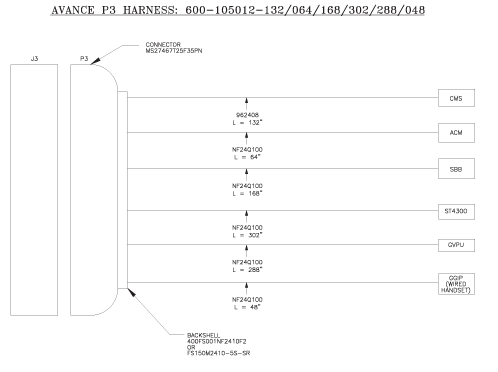
p3 harness
Example Configuration: P/N 600-105012-132/064/168/302/288/048
- Length to CMS = 132 in
» 962408 - Length to ACM = 64 in
» NF24Q100 - Length to SBB = 168 in
» NF24Q100 - Length to ST4300 = 302 in
» NF24Q100 - Length to GVPU = 288 in
» NF24Q100 - Length to GGIP = 048 in
» NF24Q100 - P3 Connector = MS27467T25F35PN
- P3 Connector Backshell = 400FS001M2410F2 or FS150M2410-5S-SR
*Max Length of 204 in
The trays are designed per the AVANCE™ system specifications; equipped with dual fans to properly cool the system, as well as a relay switch that activates the fan power when the LRU is installed. Additional custom options are available upon request.
Contact Amphenol CIT engineering to confirm the right tray for your application.
Related Products
-

Honeywell Aspire 200 Installation Kit
The Honeywell Aspire 200 Installation Kit is available in multiple configuration families, including AMT-700, AMT-3500/3800, LGA, and Basic variants. Each kit is offered with tray and cooling options such as 2 MCU S/S or S/L layouts, AC or DC fan configurations, and no-fan variants.
-
Cobham AVIATOR 200, 300 & 350 Installation Kits
Our Cobham AVIATOR 200, 300, and 350 Installation Kits are offered as a base kit with a matching tray assembly. The current configuration includes the 120-20027-102 installation kit and the P0299-101 tray assembly.
-
HS-720 Hardware Installation Kit (Unpressurized Applications)
The HS-720 Hardware Installation Kit is available in short and long 4 MCU tray configurations for un-pressurized applications. Options include no-fan, AC-fan, and DC-fan variants, allowing the kit to be matched to the required installation and cooling arrangement.